What Is an Allen-Bradley PowerFlex Drive and How Does It Work?
What Is an Allen-Bradley PowerFlex Drive and How Does It Work?
PowerFlex is Rockwell Automation's variable frequency drive family — the AC drive line you find under almost every Allen-Bradley control system from the OEM machine builder's panel up to the heavy-industry plant floor. The range stretches from sub-kilowatt fan drives to multi-hundred-kilowatt steel-mill drives, all sharing the same engineering philosophy: PWM-based motor control, vector or V/Hz operation, native EtherNet/IP integration with Logix controllers, and the kind of long-service-life industrial hardening that makes 15-year deployments routine. This guide covers what the drive does, the working principle inside, the main series in active use, and what to know when replacing one.
1. What Does a PowerFlex Drive Actually Do?
At functional level, a PowerFlex drive takes incoming AC line voltage (single-phase 100–240 V, three-phase 200–600 V, or up to 6.6 kV on medium-voltage drives), and outputs a controlled three-phase AC waveform whose frequency and voltage are independently adjustable. The motor connected to that output spins at whatever speed and torque the drive commands — not at the fixed 50/60 Hz line speed it would run at if connected directly to the supply.
That capability does three things:
- Speed control — the motor runs at the speed the process actually needs, not what the line frequency dictates
- Energy saving — fans and pumps no longer run flat-out then throttle mechanically; running at 70% speed often saves 50%+ on energy
- Soft start — motors ramp up smoothly without the 6× inrush current of across-the-line starting, which extends motor life and reduces utility demand charges
The drive also provides motor protection, fault diagnostics, and integration into the broader control system over EtherNet/IP, DeviceNet, ControlNet, RS-485 (Modbus RTU), or hardwired analog/digital I/O.
2. How It Works Inside — PWM and Vector Control
The internal architecture is essentially AC → DC → AC:
Stage 1 — Rectification (AC to DC). Incoming three-phase AC enters a three-phase full-bridge uncontrolled rectifier — a set of six diodes that convert AC to DC. The result is a DC bus voltage with some ripple, smoothed by large electrolytic capacitors. On a 480 V AC drive, the DC bus runs at approximately 680 VDC nominal.
Stage 2 — Soft start. A pre-charge circuit limits inrush current into the DC bus capacitors at power-up. Without it, capacitor charging current would be high enough to damage the rectifier diodes and weld the input contactor contacts. After the bus is charged, a relay or contactor bypasses the pre-charge resistor.
Stage 3 — Inverter (DC to controlled AC). A three-phase IGBT bridge converts the DC bus back into AC — but this time, the frequency and voltage are software-controlled through pulse-width modulation (PWM). The IGBTs switch on and off at high frequency (typically 2–8 kHz, sometimes higher), and the on-time of each switch is varied across each motor cycle to synthesize a sinusoidal waveform of the desired frequency and amplitude.
Stage 4 — Motor control algorithm. Modern PowerFlex drives use a DSP (digital signal processor) as the control core. Three control modes are common:
- V/Hz (volts per hertz) — simplest mode, maintains a constant voltage-to-frequency ratio. Adequate for fans, pumps, and basic conveyors.
- Sensorless vector control (SVC) — calculates motor flux and torque from current measurements without an encoder. Better dynamic response and low-speed torque than V/Hz.
- Closed-loop vector control — uses encoder feedback for the highest precision in speed and torque. Required for high-performance positioning and high-dynamic loads.
The vector modes regulate current, speed, and position through three nested control loops — current loop innermost, speed loop in the middle, position loop outermost where applicable.
Protection circuits. Integrated into the IGBT modules (typically IPM-based on smaller drives, discrete IGBT modules on larger ones) are overvoltage, overcurrent, overtemperature, and undervoltage detection circuits that trip the drive within microseconds of a fault to protect both the drive and the motor.
3. The PowerFlex Series at a Glance
| Series | Power range | Voltage | Typical use |
|---|---|---|---|
| PowerFlex 4M | 0.4 – 11 kW | 100–600 V | Small fans, pumps, conveyors. Example: 22F-B2P5N103 (0.4 kW / 0.5 HP) |
| PowerFlex 40 / 40P / 400 | 0.4 – 110 kW | 100–600 V | Mid-range industrial. Example: 22C-B145A103 (37 kW / 50 HP), used in extruders, spinning machines |
| PowerFlex 523 | 0.4 – 22 kW | 100–600 V | Modular V/Hz drive, easy install |
| PowerFlex 525 | 0.4 – 22 kW | 100–600 V | Vector-capable workhorse, OEM mainstream |
| PowerFlex 527 | 0.4 – 22 kW | 200–480 V | Designed for Logix PAC, programmed in Studio 5000 |
| PowerFlex 70 | 0.37 – 37 kW | 3-phase AC 380–480 V | General industrial, multiple IP ratings |
| PowerFlex 700H | Up to 270 kW (20CF1K9A0ANNENA0) | 480 V | Heavy industry, steel-mill plate rolling, descaling pumps |
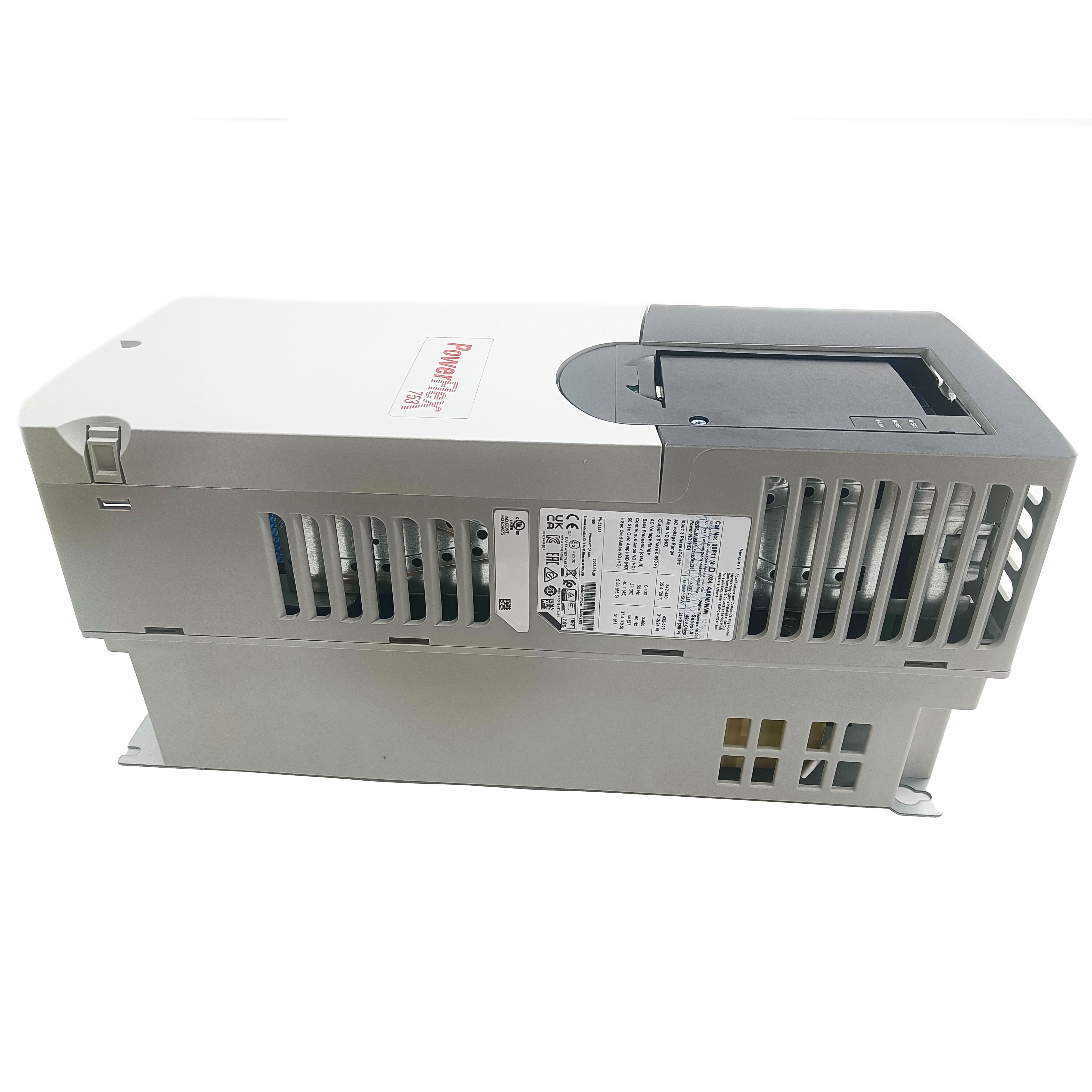
| PowerFlex 753 | Up to ~250 kW | 400–690 V | General-purpose with integrated safety |
| PowerFlex 755 / 755T | Up to several MW | 400–690 V | Architecture-class drive with predictive analytics, harmonic mitigation, regen |
| Armor PowerFlex 35 | Compact range | 480 V | IP67 distributed motor-mounted variant |
| PowerFlex 6000 / 7000 | Medium voltage | 2.3–6.6 kV | Large pumps, fans, mining, marine propulsion |
| 1336 Plus / 1336F | Legacy (e.g., 1336-15E = 15 kW) | Multiple | Older deployments still in service |
All PowerFlex models support RS-485 Modbus RTU; the 20-Series and beyond support EtherNet/IP natively and integrate seamlessly with ControlLogix and CompactLogix.
A typical efficiency figure: a 1336S-BRF20-AA at 1.5 kW and 480 V input operates at above 96% efficiency under rated load — typical of well-designed industrial VFDs.
4. Common Applications by Series
| Industry | Series typically used | What it does |
|---|---|---|
| Textile / fiber | PowerFlex 400 (22C-B145A103, 37 kW) | Precise speed control on screw extruders, raising product pass rate by ~12% in documented cases |
| Fans and pumps | PowerFlex 4M (22F-B2P5N103, 0.4 kW) | PID-controlled flow regulation, ~20% energy savings vs. throttle valves |
| Heavy industry | PowerFlex 700H (20CF1K9A0ANNENA0, up to 270 kW) | Plate-rolling descaling pumps. Tangshan Steel reported 0.3 s system response time, 35% reduction in fault rate after retrofit |
| Water and wastewater | PowerFlex 525, 753 | Pump VFDs with built-in flow optimization |
| Food and beverage | Armor PowerFlex 35, PowerFlex 525 (IP54) | Conveyor speed control, washdown-rated installations |
| Building HVAC | PowerFlex 525, 753 | Fan and pump VFDs, BACnet integration |
| Crane and hoist | PowerFlex 755 with vector control | Precise speed, regen for descending loads |
| OEM machine builders | PowerFlex 523 / 525 | Compact panel size, EtherNet/IP integration with CompactLogix |
The 700H supports programmable frequency skip bands — useful for avoiding mechanical resonance frequencies in long shaft systems. Internal filter capacitors reduce reactive losses by 15%+ on most installations.
5. Replacement and Migration Guide
Whether you're replacing a failed unit or migrating from an EOL model (PowerFlex 4 family went EOL several years back), the process follows the same shape.
Pre-replacement checklist
- Verify the new drive's voltage and power rating — exact match preferred; slight oversizing acceptable, undersizing not
- Note all parameters from the original drive — record motor data, control mode, accel/decel ramps, fault thresholds, communication settings
- Document wiring layout — power input phasing, motor leads, control I/O, communication ports
- Confirm communication protocol — Modbus RTU baud rate, EtherNet/IP IP address, ControlLogix tag mappings
- Check enclosure compatibility — newer drives sometimes have different footprints
Replacement procedure
Step 1 — Power down and isolate. Open the upstream disconnect, lock out, tag out. Wait at least 5 minutes for DC bus capacitors to discharge — the DC bus holds dangerous voltage long after AC power is removed. Verify with a meter on the DC bus terminals before touching any internal wiring.
Step 2 — Document and disconnect. Photograph the wiring before disconnecting anything. Label every wire with tape and a marker — voltages, motor phases, control I/O signals. Disconnect in this order: control wiring first, then motor leads, then incoming AC power.
Step 3 — Remove old drive. Unscrew mounting bolts. Note any thermal paste, gasket, or vibration mount on the original — these need to transfer or be replaced.
Step 4 — Install new drive. Mount in the same orientation as the original. Ensure adequate clearance for airflow — most PowerFlex drives need 50–100 mm above and below the heatsink. Tighten mounting bolts to specified torque.
Step 5 — Reconnect wiring. Reverse the disconnect order: AC power first (verify phasing), motor leads (verify rotation direction afterward), control wiring last. Tighten all terminal screws to specified torque — loose connections are the #1 cause of post-replacement faults.
Step 6 — Initial power-up. Apply AC power but keep the motor stopped. Check display for fault codes. Confirm DC bus voltage is normal (≈680 V on 480 V system). Verify cooling fan starts.
Step 7 — Configure parameters. Enter motor nameplate data first (kW, full-load amps, rated speed, rated voltage). Then control mode, ramps, fault thresholds. Finally communication settings.
Step 8 — Bench test if possible. Run the motor at low speed first with the load disconnected if possible. Verify rotation direction. Test fault response by triggering an E-stop. Only then connect the load and run at production speed.
Common migration issues
- PowerFlex 4 to PowerFlex 525: parameters transfer mostly but not all 1:1. Use Connected Components Workbench's migration tool where available.
- Older fiber-optic SCANport on 1336 Plus drives doesn't carry forward — convert to EtherNet/IP or DeviceNet at the new drive.
- Network communication: moving from DeviceNet/ControlNet to EtherNet/IP often improves diagnostics but requires PLC program updates.
6. Field Case — PowerFlex 4M Replacement on a Pump Skid
A water-treatment facility had a PowerFlex 4M (22F-B2P5N103, 0.4 kW) driving a chemical metering pump that had been in service for 11 years. The drive started displaying intermittent F4 (overvoltage) faults, clearing on power cycle, returning under specific load conditions. Diagnosis pointed to aging DC bus capacitors — typical at this age.
Decision: replace with a PowerFlex 525 in the same kW rating, taking the opportunity to upgrade EtherNet/IP integration with the plant's CompactLogix system.
Pre-work:
- Recorded all 19 active parameters from the 4M (using the keypad — old drive, no PC interface available on this model)
- Photographed the wiring layout
- Confirmed CompactLogix Studio 5000 project version was compatible with PowerFlex 525 add-on profile
Day of work:
- Total downtime: 2 hours
- Power isolation, wait for capacitor discharge (verified at 4 V residual after 5 minutes)
- Removed old 4M (DIN-rail mount, two screws)
- Mounted 525 (slightly different DIN clip pattern, used adapter rail)
- Reconnected AC input, motor leads, two control inputs (start permissive and remote speed reference)
- Powered up, entered motor data via integrated keypad
- Configured EtherNet/IP address, added to CompactLogix project
- Bench-tested at low speed, confirmed forward rotation, brought up to operating speed
Post-migration benefits:
- Drive integrated into Studio 5000 — operators can now read motor current, drive temperature, and fault history from the SCADA HMI
- Replaced a 11-year-old drive with new hardware reset the maintenance clock
- Energy monitoring data now logged to the plant historian
Total cost (drive + labor): under one day of unscheduled pump downtime.
7. Common Faults to Watch For
| Fault code | Description | Common cause |
|---|---|---|
| F4 | Overvoltage on DC bus | Regen energy with no brake resistor; failing bus caps; line voltage spikes |
| F5 | Undervoltage | Brownout; phase loss on input |
| F7 | Motor overload | Mechanical jam; undersized motor; long duty cycle |
| F8 | IGBT module fault | Short circuit on motor cable; failed IGBT |
| F12 | Heatsink overtemperature | Failed cooling fan; clogged heatsink fins; high ambient |
| F29/F30 | Analog input loss | Broken 4–20 mA reference signal wiring |
| F70 | Drive power loss | Sudden line drop during run |
Most faults clear with a power cycle after the root cause is corrected. Persistent faults usually indicate hardware degradation — bus capacitors, IGBT module, or cooling fan failure.
8. FAQ
Q: Can I use a PowerFlex 525 as a direct replacement for an older PowerFlex 40?
Yes in most cases — same kW range, similar footprint, but parameter mapping is not 1:1. Use Connected Components Workbench's drive parameter migration tool, or manually transfer parameters from the original drive's keypad readings.
Q: How much energy can a PowerFlex actually save on a fan or pump?
For variable-load fan and pump applications, switching from mechanical throttle control to a VFD typically saves 20–50% on energy. Following the fan affinity laws, halving the speed reduces power consumption to about 1/8 of full speed.
Q: Does the PowerFlex 525 work with CompactLogix PLC out of the box?
Yes. The 525 includes EtherNet/IP and an add-on profile for Studio 5000. Drag the drive into the Logix project tree, configure the IP, and full drive data is available as PLC tags.
Q: How long should a PowerFlex drive last in service?
Properly sized and installed in a clean cabinet, 15–20 years is realistic. Limiting factors are typically the DC bus electrolytic capacitors (life roughly halved per 10 °C ambient rise) and the cooling fan. Both are serviceable on most models.
Q: Why does the drive trip on F4 (overvoltage) when the motor decelerates?
Decelerating a high-inertia load pushes regen energy back into the DC bus. Without a brake resistor or regen unit, bus voltage climbs to the F4 trip threshold. Solutions: extend the decel ramp, add a brake resistor sized for the regen energy, or use a regen-capable drive like the PowerFlex 755T.
-
Posted in
Technical knowledge