

How does a servo driver work?

What Exactly is a Servo Drive?
If you've ever watched a robot arm weld a car body with millimeter precision, or seen a CNC machine carve intricate patterns into a block of aluminum, you've seen servo drives at work — you just didn't know it.
A servo drive (also called a servo amplifier) is an electronic device that controls the motion of a servo motor. Think of it as the translator between a controller's brain and the motor's muscle. The controller says, "I need the motor shaft to rotate exactly 47.3 degrees at 1,200 RPM," and the servo drive figures out exactly how much electrical current and voltage to deliver to the motor to make that happen.
Without a servo drive, a motor is essentially dumb power — it'll spin, but it won't know where it is, how fast it's going, or when to stop. The servo drive adds intelligence. It reads signals from sensors attached to the motor, compares the actual performance to the target, and makes thousands of tiny corrections per second to keep everything on track.
Quick analogy: If the servo motor is the legs of a runner, the servo drive is the brain and nervous system — constantly sensing the ground, adjusting stride length, and correcting balance in real time.
On the inside, a servo drive is a compact piece of power electronics. It contains transistors (usually IGBTs or MOSFETs) that rapidly switch the supply voltage on and off, a microprocessor that runs the control algorithms, input terminals for receiving command signals, and output terminals that connect to the motor windings. Some modern servo drives also include safety features like Safe Torque Off (STO), built-in motion controllers, and ports for industrial networks such as EtherCAT or Profinet.
How Does a Servo Drive Work?
Understanding the internal workings of a servo drive doesn't require an engineering degree, but it does help to break things down into a few stages.
Stage 1: Receiving the Command
Everything starts with a command signal. This signal comes from a motion controller, a PLC, or sometimes just a simple analog input like a ±10V signal from a joystick. Digital servo drives typically receive commands over a fieldbus network — EtherCAT, CANopen, Profinet, EtherNet/IP, or Modbus, depending on the system architecture. The command might specify a target position, a target velocity, or a target torque, depending on which operating mode the servo drive is configured for.
Stage 2: Power Conversion
The servo drive is connected to a power supply — either a DC bus shared with other drives, or directly to the AC mains through a built-in rectifier. When the drive receives a command, it uses pulse-width modulation (PWM) to chop the DC bus voltage into carefully shaped pulses that flow through the motor windings. By varying the timing and duration of these pulses, the drive controls both the amplitude and frequency of the current delivered to the motor. For a three-phase brushless motor, the drive switches three pairs of transistors in a specific sequence to create a rotating magnetic field inside the stator, which drags the permanent-magnet rotor along with it.
Stage 3: Closed-Loop Correction
Here's where things get interesting. As the motor runs, a feedback sensor (typically an encoder or resolver) mounted on the motor shaft continuously reports the actual position and velocity back to the servo drive. The drive compares this measured data against the command — and the difference between the two is the error signal. Every few microseconds, the drive adjusts its output to minimize this error. This continuous correction loop is what gives servo systems their extraordinary accuracy.
How fast is this loop? A modern servo drive can update its current control loop at frequencies as high as 16 kHz to 32 kHz — meaning it's making adjustments every 31 to 62 microseconds. Velocity loops typically run at 2–8 kHz, and position loops at 1–4 kHz. That speed is what allows servo-driven machines to track complex motion profiles with errors measured in microns.
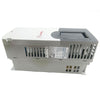
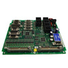
Fault Servo Driver Repair Case Study FANUC Spindle Drive System
AL-04 Alarm Fault Repair: Severe Machine Vibration Caused by Three-Phase Power Imbalance
A step-by-step diagnostic walkthrough of an AC spindle drive alarm on a FANUC Series 6 vertical machining center — from initial symptom to root cause identification and resolution.
Fault Description
A vertical machining center (VMC) equipped with a FANUC Series 6 CNC system experienced a sudden onset of severe machine vibration during a cutting operation. Simultaneously, the AC spindle drive amplifier displayed an AL-04 alarm on its status LED panel. The spindle stopped immediately, and the operator was unable to restart the machine.
The vibration was violent enough to be felt through the entire machine frame, and the sound was audibly abnormal — a clear indication that the problem was electrical rather than mechanical in origin. No recent changes had been made to tooling, workholding, or machining programs prior to the incident.
Possible Causes of AL-04
According to the FANUC AC spindle amplifier maintenance manual, the AL-04 alarm indicates a blown fuse in the three-phase AC input circuit. The following are the documented possible causes:
- 1Excessive AC power source output impedance — The input power supply has abnormally high impedance on one or more phases, causing voltage drop or imbalance that can blow the input fuses.
- 2Defective inverter transistor module — A shorted or partially failed IGBT module in the inverter stage draws excessive current, blowing the upstream fuse.
- 3Defective rectifier diode or thyristor module — A failed rectifier component causes a short-circuit path on one phase of the input power.
- 4Defective surge absorber or DC bus capacitor — A failed snubber circuit or shorted bus capacitor creates an overcurrent condition at power-up or during operation.
Diagnostic Procedure
With the four possible causes identified, the technician proceeded with a systematic, outside-in diagnostic approach — starting from the incoming power supply and working toward the drive internals. This is the recommended strategy because external causes are both more common and faster to verify.
| Phase Pair | Expected Voltage | Measured Voltage | Status |
|---|---|---|---|
| R – S | 220V AC | 220V AC | ✓ Normal |
| S – T | 220V AC | ~145V AC | ✕ Abnormal |
| R – T | 220V AC | ~120V AC | ✕ Abnormal |
The T-phase voltage was severely depressed — only about 120V instead of the expected 220V. This confirmed a significant three-phase voltage imbalance at the drive input.
| Fuse | Expected Resistance | Measured Resistance | Status |
|---|---|---|---|
| R-phase fuse | < 0.1 Ω | < 0.1 Ω | ✓ Normal |
| S-phase fuse | < 0.1 Ω | < 0.1 Ω | ✓ Normal |
| T-phase fuse | < 0.1 Ω | Several hundred Ω | ✕ High resistance |
Troubleshooting Flowchart
Root Cause Analysis
The root cause of this incident was a loose terminal screw on one phase of the three-phase fuse block in the workshop's power distribution panel. Over time — possibly due to thermal cycling, vibration from nearby equipment, or insufficient initial torque during installation — the screw connection degraded, creating a high-resistance joint.
A high-resistance connection behaves very differently from an open circuit. Rather than completely interrupting the current flow, it allows current to pass but with a significant voltage drop across the junction. In this case, the T-phase voltage at the machine input dropped from the normal 220V to only 120V. The remaining 100V was being dissipated as heat across the loose screw connection.
This type of fault is particularly dangerous for three-phase motor systems because:
1. Motor torque pulsation: An unbalanced three-phase supply creates a negative-sequence current component in the motor windings, which produces a counter-rotating magnetic field. The interaction between the forward and reverse fields causes severe torque pulsation — this is what the operator felt as "violent vibration."
2. Overheating: The motor draws excess current on the remaining healthy phases to compensate for the reduced voltage on the degraded phase. This uneven current distribution causes localized overheating in the windings and can lead to insulation failure if not corrected.
3. Drive protection trip: The FANUC spindle drive amplifier detects the input voltage imbalance and triggers the AL-04 alarm as a protective measure to prevent damage to the inverter and motor.
Resolution and Result
The loose terminal screw on the T-phase fuse in the workshop power distribution panel was re-tightened to the proper torque specification. After reconnecting power, all three phases measured 220V AC at the spindle drive input. The machine was restarted, the AL-04 alarm cleared automatically, and the spindle ran smoothly with no vibration. A test cut confirmed that machining quality was fully restored.
Preventive Measures
This type of fault is entirely preventable with proper maintenance practices. The following measures are recommended to avoid recurrence:
Scheduled torque checks: Include the workshop power distribution panel in the facility's preventive maintenance schedule. All fuse holder screws, contactor terminals, and bus bar connections should be re-torqued at least once per year, or more frequently in environments with significant vibration or temperature cycling.
Thermal imaging inspections: Use an infrared camera to scan electrical panels periodically. A loose connection will show up as a localized hot spot that is easy to identify before it causes a machine failure. Many facilities perform these scans quarterly.
Power quality monitoring: Install a three-phase power quality meter at critical machines or at the incoming service entrance. Modern monitors can log voltage imbalance events and send alerts before the imbalance becomes severe enough to trip a drive alarm.
Spring-loaded terminal blocks: When replacing fuse holders or terminal blocks, consider using spring-loaded (cage clamp) designs instead of screw-type terminals. Spring terminals maintain consistent contact pressure over time and are not susceptible to loosening from vibration.
Key Takeaways
1. Not every spindle drive alarm means the drive is broken. In this case, the fault was entirely external — a loose screw in the workshop fuse panel, not a failed component inside the FANUC drive.
2. Always measure the three-phase input power first when diagnosing spindle drive faults. It takes less than a minute with a multimeter and can save hours of unnecessary disassembly.
3. Trace faults from outside to inside: Workshop mains → Fuse panel → Transformer → Machine wiring → Drive amplifier → Motor. Stop as soon as you find the problem.
4. A high-resistance connection is often more dangerous than a clean open circuit because it can persist undetected while causing thermal damage, voltage imbalance, and intermittent faults that are difficult to reproduce.
-
Posted in
CNC Service Tech