How to Select an IGBT Module by Voltage, Current, and Switching Frequency
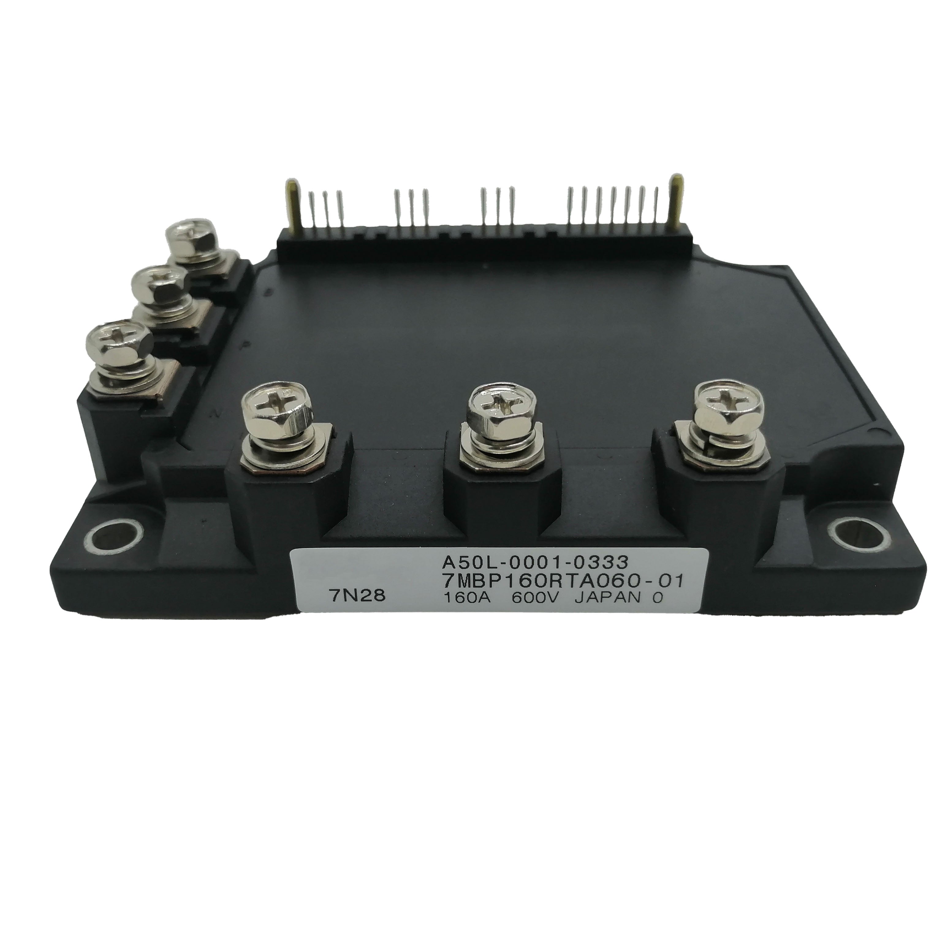
How to Select an IGBT Module by Voltage, Current, and Switching Frequency
There are dozens of parameters on an IGBT module datasheet. Three of them carry roughly 80% of the weight: voltage rating (VCES), nominal current rating (IC), and switching frequency. Get these right and the design falls into place. Get one wrong and you'll over-pay, overheat, or blow up the module.
1. What Is an IGBT Module, and Why These Three Parameters?
Q: What is an IGBT module?
A high-speed power switch packaged with multiple IGBT dies, freewheeling diodes, and a thermal baseplate in one enclosure. It combines the MOSFET's high input impedance with the bipolar transistor's low conduction voltage drop. Internal topology is usually a half-bridge or full-bridge. The module switches DC into controlled AC — that's what runs solar inverters, motor drives, and EV traction. Efficiency is above 99%, but on a 100 kW system that 1% loss is still 1 kW of heat.
Q: Why these three parameters?
They define the operating envelope. Voltage = survival. Current = thermal load. Switching frequency = loss per second. Every other datasheet parameter is downstream of these three.
2. Voltage Rating: VCES and Derating Rules
Q: What is VCES?
The max collector-emitter voltage the IGBT can block when off. Absolute max — exceed it and the device fails. Common ratings: 600 V, 650 V, 1200 V, 1700 V, 3300 V, 6500 V.
Q: How much margin do I need?
Run the DC bus at no more than 50–60% of VCES. The 40% headroom covers turn-off spikes, line surges, and bus pumping during regen.
V_DC bus, max ≤ 0.6 × V_CES
VCES Selection Table
| VCES | DC Bus Range | Typical Use |
|---|---|---|
| 600/650 V | ≤ 400 V DC | 230 V AC, low-voltage microinverters |
| 1200 V | 540–720 V DC | 380/400 V AC drives, solar, UPS |
| 1700 V | 900–1000 V DC | 690 V AC drives, wind converters |
| 3300 V | 1800–2000 V DC | Traction, MV drives |
| 6500 V | 3600–4000 V DC | HVDC, MV grid |
⚠ Watch transients. Most field failures come from brief voltage spikes exceeding VCES, not slow overload. Measure with a fast scope at the module terminals before trusting your margin.
3. Current Rating: Why the Datasheet Number Isn't Usable
Q: Can I run the rated 450 A continuously?
No. The IC rating is measured at TC = 100 °C under ideal lab conditions. Design for 50–70% of IC nom. A common shop rule: leave 30% headroom minimum — a 50 A load picks a 75 A part. For tough conditions go further.
I_application, RMS ≤ 0.5 to 0.7 × I_C nom
Q: IC, IC rms, pulse current — what's the difference?
- IC nom — DC continuous limit
- IC rms — what matters for AC output; roughly IC peak / √2
- Pulse current (ICRM) — short-duration limit, ~2× IC nom. Matters for fault survival. The short-circuit withstand time (tPSC, typically 10 µs) is the window your gate driver has to react.
4. Switching Frequency: The Trade-Off That Drives Everything
Q: Why does switching frequency matter so much?
Each on/off event dissipates energy in the silicon (Eon, Eoff in mJ). Multiply by frequency = switching loss. Double the frequency, roughly double the switching loss. A module rated 500 A at 4 kHz might only deliver 350 A at 16 kHz.
Q: What frequency suits my application?
| Application | Switching Frequency |
|---|---|
| Industrial VFD | 2–8 kHz |
| HVAC compressor | 4–16 kHz |
| Solar inverter | 8–20 kHz |
| UPS | 10–20 kHz |
| Welding inverter | 20–50 kHz |
| EV traction | 5–20 kHz |
| Induction heating | 20–100+ kHz |
| Railway traction | 0.5–2 kHz |
IGBT Type vs Frequency
- Low-speed IGBT: low switching loss, suits ≤10 kHz applications
- Trench IGBT4 (drives): balanced, 2–20 kHz
- High-speed IGBT: short turn-on time, suits ≥20 kHz
- SiC MOSFET: 20–100+ kHz, 2–4× cost premium
💡 Tip: If pushing the upper frequency edge, switching loss exceeds conduction loss. Move to a high-speed IGBT (H/HS suffix) or SiC.
5. The Gate Driver — Often Overlooked, Often the Real Bottleneck
Q: Why does the gate driver matter for module selection?
The IGBT can only perform as well as the gate driver lets it. A cheap generic driver paired with a premium 1200 V / 1200 A IGBT will throw away most of what you paid for. The driver determines switching speed, dv/dt immunity, and short-circuit response.
Q: What gate driver specs should I check against the IGBT?
Three things:
- Peak drive current. A 1700 V / 1200 A class IGBT needs roughly 20 A peak to switch cleanly. Undersized drivers stretch the switching transition and burn extra loss in the IGBT.
- CMTI (common-mode transient immunity). For high-side switching in half-bridges, look for >150 kV/µs. Lower CMTI means the driver gets falsely triggered by the very dv/dt it's supposed to control.
- Short-circuit response time. Must fit inside the IGBT's tPSC (typically 10 µs) with margin. A driver that takes 12 µs to react can't save a 10 µs IGBT.
Q: How much does a good driver really help?
Field measurements on a three-phase inverter test rig: switching to a properly-matched professional driver (Power Integrations CONCEPT 2SP0320T2A0-17 class) versus a generic driver board dropped the IGBT case temperature by ~12 °C under the same load. That's the difference between hitting your design Tj target and not.
The same setup also benefits from dual-channel independent supplies for upper and lower bridge (cleans up timing), low-inductance PCB layout in the gate loop (less ringing), and tight gate-emitter routing.
6. How Everything Interacts in Practice
Q: Why isn't selection trivial once I have voltage, current, frequency?
Because they share a thermal budget. Total loss = conduction + switching. The heat flows through the silicon-to-heatsink path, and junction temperature must stay below 150 °C (130 °C absolute for some older parts).
P_total = P_cond + P_sw
P_cond ≈ V_CE(sat) × I_avg × duty
P_sw ≈ (E_on + E_off) × f_sw

T_j = T_ambient + P_total × (R_th(j-c) + R_th(c-s) + R_th(s-a))
VCE(sat) is typically 1.5–2.0 V at rated current. Rth(j-c) for the FF450R12KE4 is 0.058 K/W per IGBT.
Selection is iterative: pick a candidate, calculate losses, check Tj. If too hot, step up.
7. Worked Example with a Real Module
Case: 200 kW VFD, 400 V AC three-phase supply. Candidate: Infineon FF450R12KE4 (1200 V / 450 A, EconoDUAL 3).
Step 1 — Voltage
DC bus ≈ 540 V nominal, transient up to 600 V. 600 ÷ 0.6 = 1000 V minimum VCES. 1200 V module fits. ✓
Step 2 — Current
I_line = 200,000 / (√3 × 400) ≈ 289 A RMS
289 ÷ 0.6 ≈ 482 A minimum I_C nom
The 450 A FF450R12KE4 is marginal. The 600 A FF600R12ME4 is safer for 200 kW. FF450R12KE4 fits 150–175 kW.
Step 3 — Frequency
4 kHz typical for VFDs. IGBT4 silicon is optimized for 2–20 kHz. ✓
Step 4 — Thermal
ΔT_j-c = 350 W × 0.058 K/W ≈ 20 °C. Plus interface (~6 °C), plus sink-to-ambient (~35 °C at 40 °C ambient) → Tj around 100–105 °C. Within 125 °C design target. ✓
For higher-power example: for designs in the 250–400 kW range with wider operating temperature (−10 °C to 130 °C), the 1200 V / 800 A class (e.g. FF800R12KE7) covers PV inverter DC bus fluctuation and rail traction frequent start/stop without high-temperature derating.
✅ Answer: For 200 kW use FF600R12ME4. For 150–175 kW use FF450R12KE4. For >250 kW step up to 800 A class.
8. Handling and Protection Notes
A module that survives selection still has to survive installation and maintenance:
- ESD sensitive. Always wear an anti-static wrist strap when handling. Static discharge through the gate is the most common shipping/install failure.
- Solder temperature. When mounting terminals, keep iron temperature ≤ 260 °C and contact time short. Excessive heat cracks the package.
- Gate drive voltage. VGE should stay within ±20 V. Beyond that, the gate oxide breaks down — permanent failure.
- Operating temperature. Don't exceed the rated Tj max (150 °C for most modern parts, 130 °C for some older types). Check heatsink fans and thermal paste during scheduled maintenance.
- Date code preference. For long-life equipment, favour newer production batches — material consistency improves over revisions.
9. Common Selection Mistakes
- Sizing IC at the rated condition. Lab spec ≠ real installation. Always derate 50–70%.
- Ignoring voltage transients. Most "random failures" are missed turn-off spikes. Scope the module terminals.
- Wrong IGBT generation for the frequency. IGBT4 at 30 kHz overheats. High-speed IGBT at 2 kHz wastes money on higher VCE(sat).
- Underspec'd gate driver. Premium IGBT + cheap driver = mediocre system. Match driver peak current and CMTI to the module class.
- Forgetting the short-circuit budget. A 12 µs driver response can't save a 10 µs tPSC module.
- Over-spec'ing "to be safe." A 1700 V module on 540 V bus has higher VCE(sat) and more gate charge. Bigger isn't always better.
10. Quick Checklist
| Step | Check | Rule |
|---|---|---|
| 1 | DC bus (with transients) | V_bus ≤ 60% × V_CES |
| 2 | RMS load current | I_RMS ≤ 50–70% × I_C nom |
| 3 | Switching frequency | Match IGBT generation |
| 4 | Loss calculation | From datasheet curves |
| 5 | Junction temperature | T_j ≤ 125 °C target |
| 6 | Gate driver | Peak current + CMTI matched |
| 7 | Short-circuit vs driver | Driver response < t_PSC |
| 8 | Package & mounting | Footprint + ESD/torque compliant |
| 9 | Lifecycle status | Avoid EOL parts, prefer recent batches |
Bottom Line
Three derating rules cover most of it: 60% of VCES, 50–70% of IC nom (or "leave 30% headroom"), and match silicon generation to switching frequency. Then pick a gate driver worthy of the IGBT — that one decision alone can drop case temperature 10 °C.
The right module is rarely the cheapest one that meets minimum specs. It's the one with margin for thermal cycling, ambient swings, and slow degradation over years.
If you're sizing for a specific application, share the DC bus voltage, RMS current, switching frequency, ambient conditions, and gate driver in mind. We supply Infineon, Mitsubishi, Fuji, and Semikron-Danfoss IGBT modules with verified datasheets.
-
Posted in
Technical knowledge