

What Is The Difference Between Servo Motor And Stepper Motor?
1. Servo Motor Operating Principles & Internal Architecture
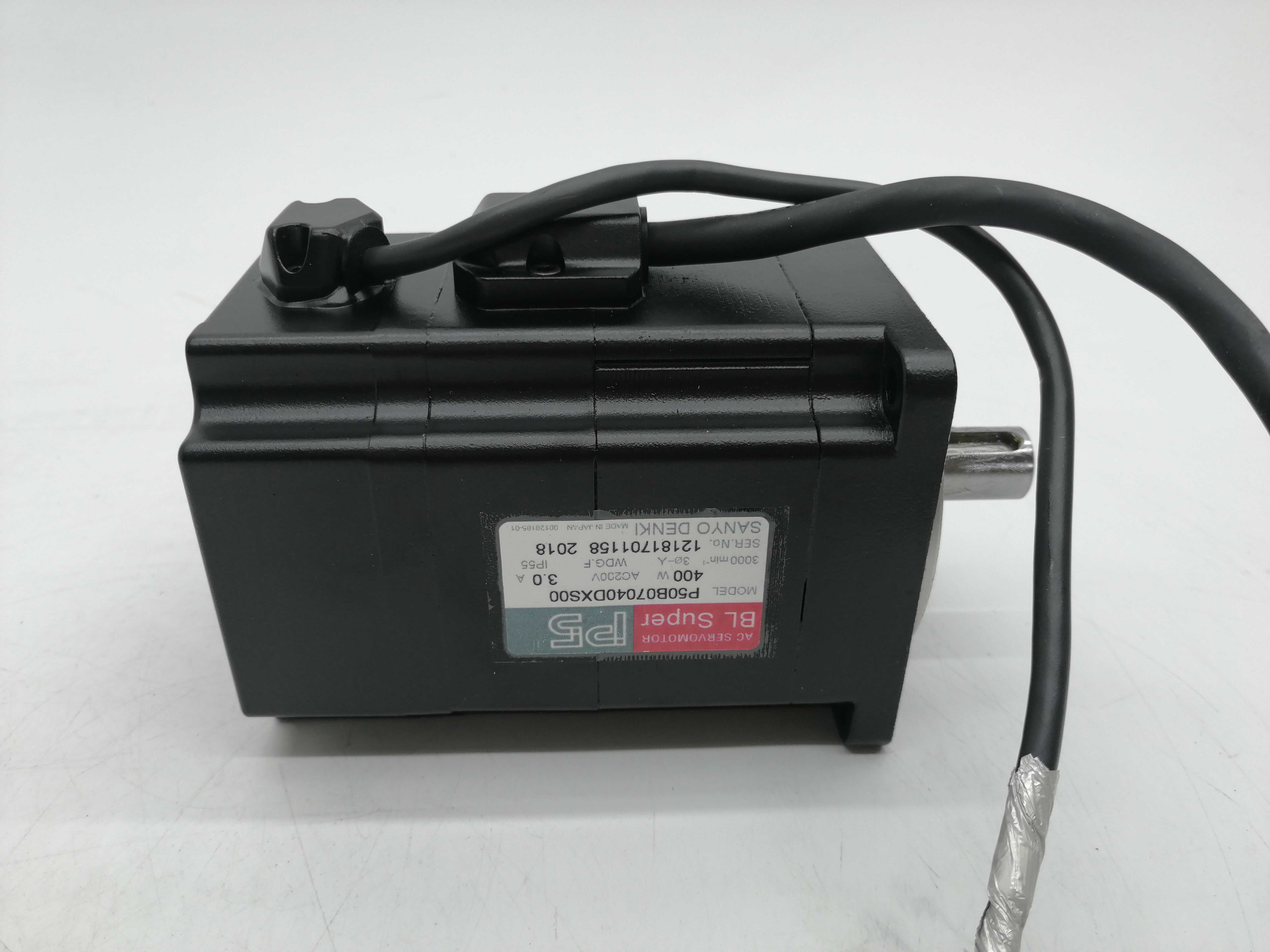
A servo motor isn't a single type of motor — it's a motor that's been paired with a feedback device and an intelligent drive to create a closed-loop motion control system. That said, the overwhelming majority of industrial servo motors today are AC permanent magnet synchronous motors (PMSM). Understanding their internal architecture explains why they behave the way they do.
The stator of a typical AC servo carries three-phase copper windings, just like an induction motor. The difference is in the rotor. Instead of aluminum bars or copper squirrel cages, a servo rotor contains high-energy rare-earth magnets — usually neodymium-iron-boron (NdFeB) alloy — arranged in either a surface-mount or interior permanent magnet (IPM) configuration.
Surface-mount designs glue or band magnets to the outside of the rotor lamination stack. They're simpler to manufacture and produce a sinusoidal back-EMF waveform, which makes for smooth low-speed operation. IPM designs embed the magnets inside the rotor, which adds reluctance torque on top of the magnet torque, giving you a wider constant-power speed range. Most modern high-performance servos above 1 kW use IPM architectures.
Because the rotor field comes from permanent magnets rather than induced current, there's zero slip — the rotor turns at exactly the speed of the rotating stator field. This is what makes synchronous motors so precise and efficient compared to induction motors, where the rotor always lags the field slightly.
2. Closed-Loop Control: How Servo Feedback Actually Works
The "magic" of a servo motor is really just aggressive, high-speed error correction. Every few microseconds, the system reads where the motor actually is, compares that to where it should be, and adjusts the current to close the gap. This happens through a cascaded control loop — three nested feedback loops, each running at a different bandwidth.
The innermost loop — the current (torque) loop — runs at the highest bandwidth, typically 8–32 kHz. It uses Field-Oriented Control (FOC) to decompose the three-phase stator current into two components: one that produces torque and one that controls the magnetic field. This is where the real-time "muscle" of the servo lives.
Wrapped around that is the velocity loop, running at 2–8 kHz. It reads the encoder's speed data and adjusts the torque command to maintain the target velocity. When you hit a bump in the load, this loop reacts in sub-millisecond time to push more current and keep the speed on track.
The outermost position loop runs at 1–4 kHz. It compares the actual encoder position to the commanded position and generates velocity commands to close the gap. This is the loop responsible for the "hit your mark every time" precision that servos are known for.
When vendors quote "response bandwidth" or "position loop gain," they're describing how aggressively these loops can correct errors. Higher bandwidth = faster correction = better performance under varying loads. But higher bandwidth also requires better mechanical stiffness in the coupling and frame, or the system will oscillate. This is why motor selection and machine design must happen together — not in isolation.
3. Key Performance Parameters & How to Read a Torque Curve
Every servo motor datasheet gives you a torque-speed curve. If you only learn one technical concept from this article, make it this one — it's the single most important tool for evaluating whether a motor fits your application.
The Parameters That Actually Matter
Some vendors spec "peak torque" prominently on the first page and bury continuous torque in the appendix. Your machine runs on continuous torque, not peak. Always size your motor on the continuous rating, then verify the peak is enough for your acceleration and deceleration ramps.
4. Servo Motor vs. Stepper Motor: Full Technical Comparison
I've put together a detailed comparison based on actual spec-sheet data from leading manufacturers. This isn't theory — it reflects the motors you'd actually be quoting from vendors like Yaskawa, Siemens, Mitsubishi, and Oriental Motor.
| Parameter | Servo Motor (AC PMSM) | Stepper Motor (Hybrid) | Advantage |
|---|---|---|---|
| Control System | Closed-loop (encoder required) | Open-loop (encoder optional) | Stepper simpler |
| Position Accuracy | ±0.01° to ±0.005° (encoder-dependent) | ±1.8° full step; ±0.09° w/ 20× microstepping | Servo under dynamic load |
| Repeatability | ±1 encoder count (sub-arc-minute) | ±0.05° (no cumulative error per cycle) | Servo |
| Speed Range | 0–6,000 RPM (some to 10,000+) | 0–1,200 RPM practical max | Servo |
| Torque at Low Speed | Full rated torque | Full rated torque (natural holding) | Tie |
| Torque at High Speed | Flat curve to rated speed | Drops sharply above 500–800 RPM | Servo |
| Peak / Overload Torque | 200–300% of rated for 1–3 sec | None — stalls if exceeded | Servo |
| Holding Torque (zero speed) | Requires power + active control | Natural holding via detent + energized coils | Stepper |
| Energy Efficiency | 85–95% (draws only needed current) | 50–70% (constant full current draw) | Servo |
| Heat Generation | Low (current proportional to load) | High (full current even at standstill) | Servo |
| Resonance Issues | None (damped by feedback loop) | Yes — at mid-range speeds (100–300 RPM) | Servo |
| Missed Steps / Lost Position | Impossible (alarm triggers on excess error) | Possible under overload (silent failure) | Servo |
| Physical Size (same torque) | Larger (includes encoder) | More compact (no feedback device) | Stepper |
| System Cost (≤500W) | $300–$800 (motor + drive + encoder) | $50–$200 (motor + drive) | Stepper |
| System Cost (2+ kW) | $800–$3,000+ | Rarely available at this power | Servo (only option) |
| Commissioning Complexity | Requires gain tuning (PID + filters) | Plug-and-play in most cases | Stepper |
5. Motor Sizing: The Math Behind the Selection
Before you send an RFQ to your vendor, your engineering team should have run a sizing calculation. Here's the fundamental process — simplified but accurate enough to sanity-check what your engineers or vendors are proposing.
Step 1: Calculate the Load Torque
where F = force at the load point (N), r = radius of pulley/ballscrew lead (m)
For rotary loads:
T_load = J_load × α + T_friction [Nm]
where J_load = load inertia (kg·m²), α = angular acceleration (rad/s²)
Step 2: Calculate the Acceleration Torque
α = Δω / Δt [rad/s²]
where Δω = speed change (rad/s), Δt = acceleration time (s)
Step 3: Check the Inertia Ratio
Ratio = J_load / J_motor
Rule of thumb:
≤ 5:1 → Good (easy to tune, stable)
5:1 – 10:1 → Acceptable (needs careful tuning)
> 10:1 → Risky (oscillation likely, consider gearbox)
The inertia ratio matters enormously. A motor trying to control a load with 20× its own inertia is like a small dog trying to steer a shopping cart — technically possible, but jerky, slow to respond, and likely to overshoot. Adding a gearbox between motor and load reduces the reflected inertia by the square of the gear ratio, which is why you'll often see a 5:1 or 10:1 planetary gearbox spec'd alongside a servo motor.
6. Four Real-World Case Studies with Performance Data
Servo-Driven Press Replaces Hydraulic Cylinder
An EV battery module assembly plant in Michigan needed to press cell modules into casings with a precise 12 kN force — but the hydraulic presses were leaking fluid onto the clean-room floor and couldn't hit the ±0.1 mm position tolerance consistently.
The team replaced each hydraulic press with a servo motor driving a ball screw actuator. The servo's torque monitoring provided real-time force feedback, catching under-insertion and over-insertion events that the hydraulic system couldn't detect.
The servo system cost roughly 3× the hydraulic hardware, but the elimination of hydraulic fluid maintenance, leak cleanups, and the 62% energy reduction brought the payback to under a year.
Stepper-to-Servo Upgrade Eliminates Label Skew
A beverage producer's labeling line was running stepper motors at 350 bottles per minute. At that speed, the steppers were operating near their torque falloff zone. Label placement accuracy was drifting ±2.5 mm — enough to trigger retail rejection on about 4% of output.
After switching to 400W AC servo motors with 17-bit absolute encoders, the label accuracy tightened to ±0.3 mm, and the line speed increased to 500 bottles per minute without any mechanical changes.
Multi-Axis Servo Coordination for 300mm Wafer Transport
A semiconductor fab in Taiwan spec'd a new 300mm wafer transport robot. The critical requirement: ±0.025 mm repeatability on a 4-axis SCARA arm, with a complete pick-place cycle under 3 seconds. The environment was ISO Class 4 cleanroom, so the motors needed to be fully sealed with no outgassing.
The design used four Yaskawa Σ-7 servo motors with 24-bit absolute encoders (16.7 million counts per revolution). EtherCAT communication synchronized all four axes with sub-microsecond timing. Motor selection was driven primarily by inertia matching — the gearboxes were sized to keep reflected inertia below a 3:1 ratio on every axis.
Stepper motors were never considered — at these speeds and precision levels, closed-loop servo is the only viable technology. The encoder alone costs more than a complete stepper system, but a single scratched wafer can cost $5,000–$25,000, so the investment is trivial relative to the risk.
Closed-Loop Steppers: The Middle Ground That Worked
A diagnostics equipment manufacturer needed to move pipette heads across a 384-well microplate with ±0.05 mm accuracy at moderate speed (200 mm/s max). The team debated between stepper and servo for months.
The solution was a closed-loop stepper motor — a hybrid stepper with a 1,000-line incremental encoder and a drive that monitors position and corrects missed steps in real time. Total per-axis cost was about 40% of an equivalent servo system, and the mounting envelope was 30% smaller — a decisive advantage inside the instrument's compact chassis.
The takeaway: closed-loop steppers occupy a growing niche between traditional open-loop steppers and full servo systems. For loads under 500W with moderate speed demands, they're worth serious consideration.
7. Decision Framework: Picking the Right Motor
After reviewing dozens of projects, I've found that the motor choice usually boils down to answering five questions. Run through them in order — by the time you reach question three, the answer is usually clear.
| # | Question | If YES → Likely Choice | Notes |
|---|---|---|---|
| 1 | Does the application require sustained speeds above 1,000 RPM? | Servo | Stepper torque collapses above ~1,000 RPM. Non-negotiable. |
| 2 | Does the load vary significantly during operation? | Servo | Variable loads risk stalling steppers. Servo's feedback handles it. |
| 3 | Is a missed step / lost position a safety or quality risk? | Servo | Safety-critical = closed-loop. No exceptions. |
| 4 | Is the motion profile simple point-to-point at low speed? | Stepper | Simple, predictable profiles are the stepper's sweet spot. |
| 5 | Is total system cost the dominant constraint? | Stepper (with encoder if needed) | Consider closed-loop stepper as a middle-ground compromise. |
One final thought from the field. I've noticed that teams tend to default to whichever technology their last project used. Automotive shops reach for servos even when a stepper would do. Maker-culture teams spec steppers for jobs that clearly need servo performance. The best projects start with the application requirements and work backward to the motor — not the other way around.
The servo motor market is approaching $20 billion globally, and the technology is evolving fast — silicon-carbide drives, 24-bit encoders, IIoT-connected predictive maintenance, and increasingly blurred lines between steppers and servos. Whatever you're building next, there's almost certainly a motor that fits. The trick is asking the right questions before you write the purchase order.
-
Posted in
Technical knowledge